OUR LOCATIONS
We can provide our services to power plants worldwide
Bradenton, Florida
941 - 527 - 6196
941 - 755 - 5229 (FAX)
Milwaukee, Wisconsin
414 - 698 - 5644
|

VIBRATION DIAGNOSTICS
Vibration analysis is one of many important tools to help solve a rotor-bearing dynamic issue. But it is important to remember that vibration is only a symptom! Vibration is never a separate issue in and of itself, and the typical first reaction to "balance it" without identifying the root cause can often lead to more damage down the road.
Vibration diagnostics are the key to identifying the proper course of action, of which balancing is just one possibility. At Z-R Consulting, we collect and analyze all pertinent vibration data, including:
- Vibration amplitudes through all speeds, with two probes per axial location if at all possible
- Shaft orbits through all speeds
- DC Gap voltage trends for proximity probes
- Shaft centerline position through all speeds
- Phase angle through all speeds
- Bearing and pedestal seismic readings
- Bode, Polar, Shaft Centerline, and Full Frequency Spectrum plots
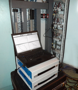
Z – R Consulting uses Bently Nevada vibration monitoring and diagnostic tools to interface with the plant’s integrated vibration monitoring system. If needed, we also carry portable seismic sensors to measure bearing and pedestal vibration.
We can also perform blade impact testing to measure blade axial and torsional resonances.
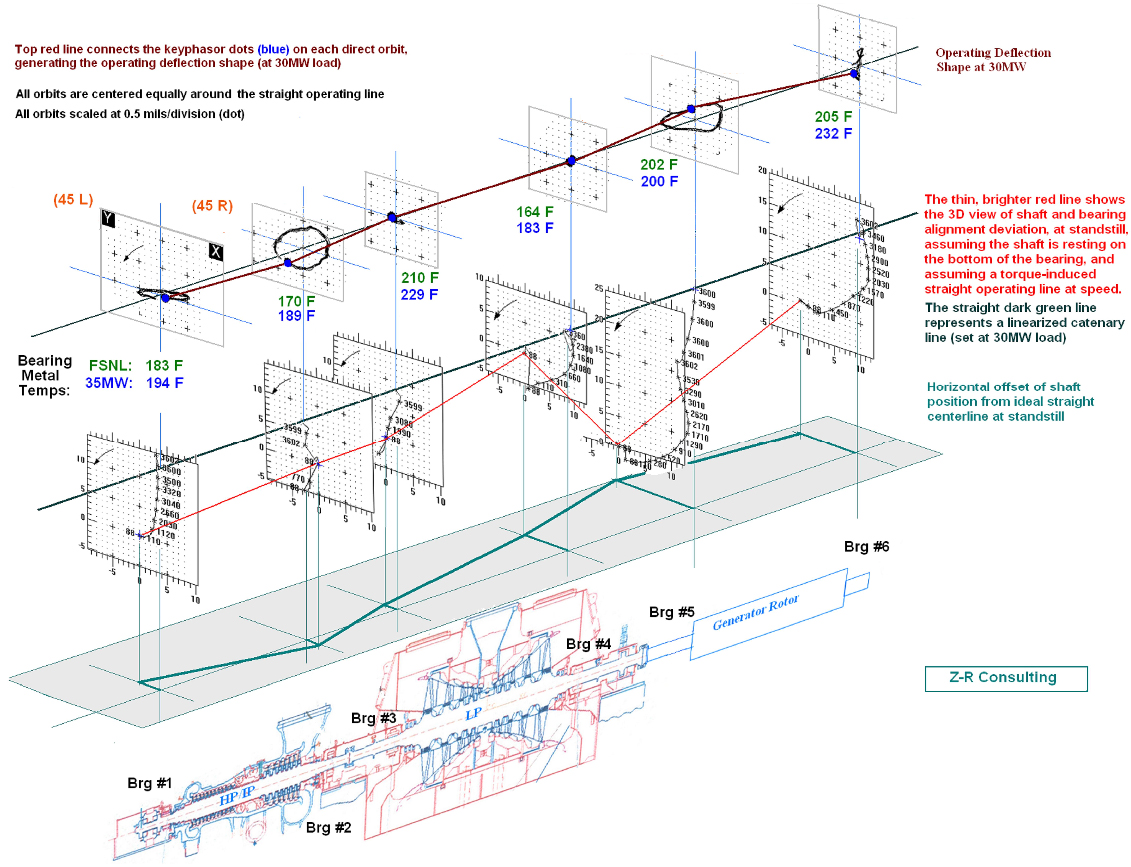
In addition to the usual use of vibration data for critical speeds and for balancing calculations, many other parameters can be discerned. For example, a relation of the amplitude trend versus phase in a Bode plot and polar plot provides a clear and typically-overlooked indication of a rotor bow or eccentricity, separate from “unbalance”. The size and shape of the shaft orbits, combined with shaft centerline paths can be used to identify the operating deflection shape (ODS), and can identify misalignment problems, improper bearing preloads, or too tight or loose clearances. The full frequency spectra, showing both forward and reverse precession harmonics, can point to rubs or other shaft disturbances.
Especially valuable, this data can clearly indicate whether the rotor has a static or dynamic problem. A static problem would be an internal rotor deformation, such as a bow, bent coupling, off-center journals, locked generator wedges, etc., that is statically connected to the rotor. A dynamic problem would be something dependent on operation, such as a bearing stability/design issue, steam flow problem, lube oil issue, or similar. This data can also indicate whether the root of the problem is an misalignment or bearing position issue. (See the image below, which presents the ODS at load, as well as the "cold" alignment position of the bearings, and the resulting rotor train position.)
While it is easy to observe what is shaking during operation, the real art is to find the root cause of potential problems ahead of time in the shop, recognizing and eliminating them. Through proper, thorough runout readings, appropriate machining corrections and/or the correct balancing method, all “static” problems with the rotor can be prevented and eliminated, even before reinstallation.
|